


How to Prevent Condensation on TECs: Four Root Causes & Troubleshooting Guide
Welcome to our TEC knowledge sharing session! During the commissioning of thermoelectric cooling projects, condensation on TECs is a common issue. In most cases, condensation does not mean the TEC itself is defective. Instead, it stems from design oversights in temperature control logic, sealing structure, thermal insulation scheme or air duct layout. Drawing on on-site engineering commissioning experience, this article outlines the root causes of condensation and a step-by-step troubleshooting process. Feel free to leave a comment if you have questions or wish to learn more about TECs.
1. The Fundamental Principle of TEC Condensation
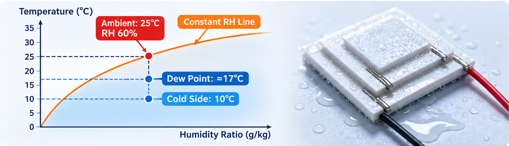
Air can hold a limited amount of water vapor, and this capacity decreases as temperature drops. When a solid surface is cooled below a critical temperature, the air can no longer retain all its moisture. Excess water vapor separates out and forms droplets — this critical temperature is the dew point.
Condensation will occur if the cold surface temperature falls below the ambient dew point. For example, at an ambient temperature of 25°C and 60% relative humidity, the dew point is approximately 17°C. If the cold side stabilizes below 10°C, the risk of condensation rises sharply. In high-humidity conditions such as the plum rain season in southern China, the dew point is higher, condensation forms faster, and water accumulation becomes more severe.
2. Troubleshooting Causes & Mitigation Measures
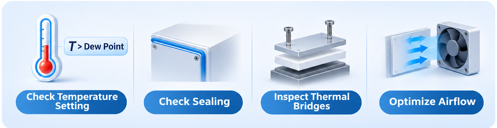
1.Excessively low target temperature on the cold side (most frequent cause) Chasing ultra-low temperatures by setting the cold-side target far below the dew point, or running continuously near 0°C.
Mitigation: Evaluate actual process requirements and verify whether such low temperature is mandatory. Raise the cold-side setpoint as long as component temperature specifications are met. Keep the cold surface temperature above the ambient dew point with a safety margin of 2–3°C.
2.Defective housing sealing Splitting seams, openings and cable feedthroughs on the enclosure act as channels. Moist ambient air keeps leaking into the internal cavity, and water vapor continuously condenses near the cold zone once the TEC starts cooling.
Mitigation: Inspect housing joints and gaskets for integrity. Cable feedthroughs are key checkpoints, as moisture easily seeps in along gaps around wires.
3.Thermal bridging effect Insulation is only applied to the TEC itself, while metal components such as brackets, fastening screws and thermal blocks remain thermally unisolated. Cold spreads through these metal paths, bringing component temperatures below the dew point and causing condensation outside the TEC.
Mitigation: Confirm thermal gaskets are installed between the cold side and enclosure / mounting substrate. Ensure insulation fully covers edges and fasteners.
4.Poor air duct design Fans blow untreated humid ambient air directly onto the exposed cold plate, worsening condensation.
Mitigation: Check whether humid airflow hits the cold side directly and whether hot and cold air ducts cross-talk. Enclose the cold zone if necessary to avoid direct contact between moist air and low-temperature surfaces.
Summary
Condensation on TECs is essentially a thermal management system design issue. Improvements focus on four aspects: temperature setpoint review, sealing inspection, thermal bridging elimination and air duct optimization. If you encounter condensation during TEC cooling operation, follow this step-by-step checklist and apply corresponding countermeasures.