
TEC Science Class:When choosing refrigeration tablets, these four performance parameters must be looked at!
Welcome to TEC Science Lesson! Last week, we learned about the working principle and basic structure of the semiconductor refrigerator, and this class will continue to introduce its key parameters and performance.
1、Relevant performance parameters of thermoelectric refrigerator
When choosing a semiconductor cooler, its comprehensive performance (such as cooling capacity, heat dissipation capacity, etc.) is our focus. The comprehensive performance of the semiconductor refrigerator is mainly determined by the four performance parameters of Imax, Vmax, DTmax and Qcmax. Let's take a look at what these parameters represent.
①Imax (maximum current) : the current value passing through TEC when the temperature difference ΔT between the heat releasing surface and the heat absorbing surface reaches its maximum. At this time, the heat absorption Qc of TEC is 0. Imax reflects the current limit of TEC at the maximum temperature difference.
②Vmax (maximum voltage) : The voltage value at both ends of TEC when the maximum current value Imax is connected. At this time, the heat absorption Qc of TEC is 0. Vmax reflects the voltage limit of TEC under the maximum current condition.
③DTmax (maximum temperature difference) : When the maximum current value Imax is switched on, the maximum temperature difference ΔT(Th-Tc) between the heat releasing surface and the heat absorbing surface of TEC. At this time, the heat absorption Qc of TEC is 0. DTmax reflects the maximum cooling capacity of TEC. In general, under the premise of the same hot surface temperature, the larger the DTmax, the better the performance of the semiconductor material.
④Qcmax (maximum cooling power) : the heat absorption of TEC when the maximum current value Imax is connected. At this time, the temperature difference ΔT between the endothermic and exothermic surfaces is 0. Qcmax reflects the maximum cooling capacity of TEC under optimal operating conditions.
In general, we can comprehensively evaluate the performance of TEC according to the above four key parameters to ensure that it achieves the desired cooling effect in practical applications.
2、Teach you how to calculate /TEC-12706
The performance parameters of TEC can be obtained not only by simulation calculation, but also by experiment test. The following table shows the performance parameters of TEC-12706 at the hot surface temperature Th=50℃. Then, given the maximum temperature difference/maximum cooling capacity, how can other performance parameters be derived? Little cool will show you by applying the formula.
▲ TEC-12706 Performance parameters
Application formula:
●DT=Th-Tc, that is, temperature difference = hot surface temperature - cold surface temperature
●V=Sm*DT+I*Rm that is, input voltage = temperature difference power generation + Ohm's law
●Qh=Qc+V*I, that is, heat discharge = heat absorption + voltage * current
* Where Sm is the Seebeck coefficient of the semiconductor material and Rm is the resistance of the semiconductor cooler, both of which are dynamic values that change with temperature.
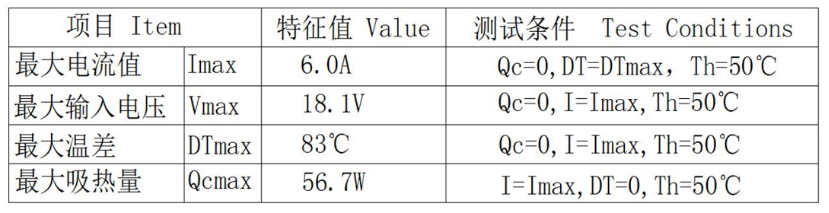
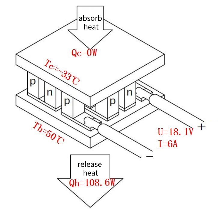
① When the maximum temperature difference DTmax=83℃, Qc=0
Tc=Th-DT=50℃-83℃=-33℃
I=Imax=6.0A,V=Vmax=18.1V
Qh=Qc+V*I=0+18.1V*6A=108.6W
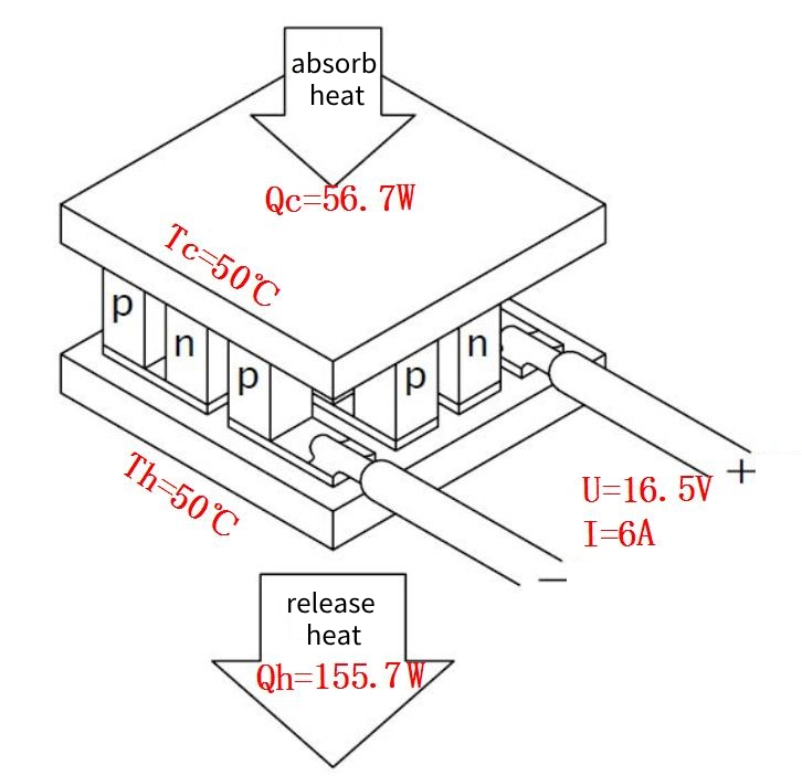
②When the maximum cooling capacity Qcmax=56.7W, DT=0
Tc=Th-DT=50℃-0=50℃
Qc=Qcmax=56.7W, I=Imax=6.0A
V = Sm*DT + I*Rm = Sm*0+6A*2.75Ω=16.5V
Qh=Qc+V*I=56.7W+16.5V*6A=155.7W
3、Understand the performance diagram /TEC-12706
In addition to calculation, you can also comprehensively understand the performance of TEC under different working conditions by consulting four performance relationship diagrams (Qc, V, Qh, COP& I) (all under a certain hot surface temperature). In actual application scenarios, it helps users optimize TEC application configurations.
①Qc VS I diagram: The relationship between input current and cooling power under different temperature differences ▼
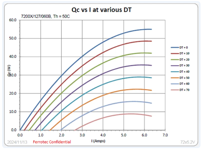
• Curve use: Verify that the TEC has sufficient cooling capacity to meet application requirements.
• Verify cooling capacity: Ensure that the cooler can provide sufficient cooling power.
• Select the right operating point: Find the best combination of input current and temperature difference to enable TEC to operate within the high efficiency range.
②Qh VS I diagram: The relationship between the input current and the heat dissipation power of the hot surface under different temperature differences ▼
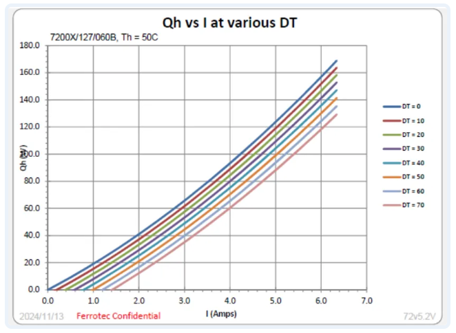
• Curve use: Confirm that the heat sink has sufficient heat dissipation capacity to meet the application requirements.
• Confirm heat dissipation capacity: Ensure that the heat dissipation power is sufficient for the system to effectively handle the heat generated by the TEC.
• Select the right working point: according to the actual cooling effect, find the corresponding input current and the corresponding heat surface heat dissipation power.
③V VS I diagram: The relationship between input current and voltage under different temperature differences ▼
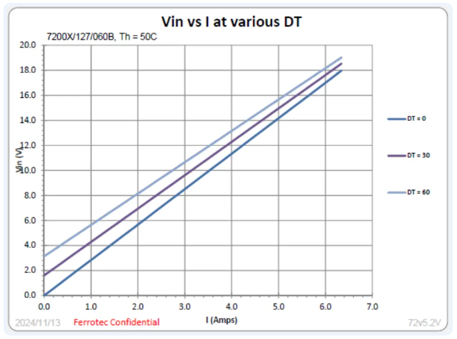
• Curve use: After selecting the TEC model, determine the power supply voltage value it needs under specific operating conditions.
• Select the appropriate operating point: The user can first determine the appropriate input current and temperature difference through the Qc VS I curve, and then find the corresponding supply voltage value through the V VS I curve to ensure that the supply voltage matches the operating voltage of the TEC.
• Optimize the power supply configuration: By selecting the power supply voltage properly, TEC can work in the high efficiency range to avoid inefficiency or equipment damage caused by insufficient or excessive voltage.
④COP VS I diagram: The relationship between input current and COP (cooling efficiency) under different temperature differences ▼
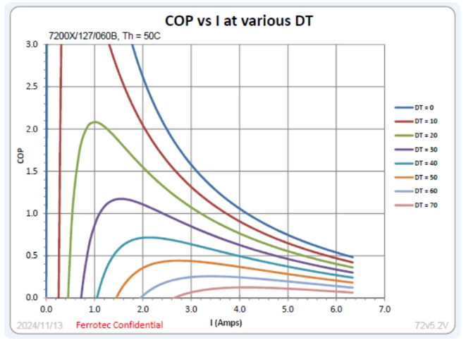
• Curve use: Determine the COP (COP coefficient is the ratio of cooling power to input power) to maximize cooling capacity and minimize input power (power consumption).
• Determine the optimal operating point: The user can find the maximum COP value at a specific temperature difference through the curve, select the corresponding input current, and ensure that the TEC works in the high efficiency zone.
• Optimize energy consumption: Adjust the input current to minimize the input power (reduce power consumption) while providing sufficient cooling power to improve the overall efficiency of the system.
Next notice
In this TEC science class, we learned the key performance parameters and performance relationships of semiconductor coolers together. The next issue will bring you the advantages and application examples of semiconductor refrigeration technology (TEC), so stay tuned!