


TEC Science Class 丨 Why Is Your TEC Cooling Module Under‑performing? Three Root Causes
Thermoelectric Coolers (TECs) are deployed across a wide range of applications, and cooling module specifications vary for different equipment. Even identical‑model devices may be fitted with different TEC units. Two devices with similar appearances can deliver vastly different cooling performance. This article elaborates on key factors that govern TEC cooling performance. Feel free to leave comments if you have questions or wish to learn more about TEC technology.
1. Thermal Grease: Coating Thickness and Assembly Clearance
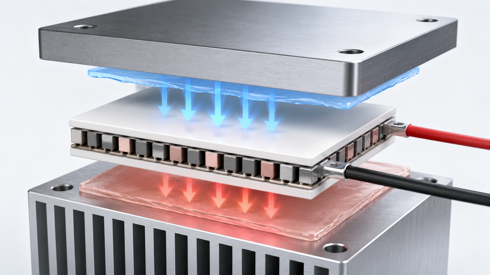
Thermal grease is the most common thermal interface material between a TEC and cold‑conducting components. Without thermal grease, micro‑gaps at contact surfaces severely impede heat and cold transfer. The cold and heat generated by the TEC cannot be efficiently conducted, resulting in substantial degradation of overall system performance. While most engineers recognize the necessity of thermal grease, practical implementation details are frequently overlooked:
☑️ Control coating thickness precisely: Excessively thick thermal grease degrades thermal conductivity. Squeezed‑out grease may create a thermal bridge between the hot and cold sides of the TEC, allowing heat from the hot side to leak back to the cold side and reduce cooling capacity. Apply a thin, uniform layer sufficient only to fill microscopic surface gaps; avoid building up an overly thick interface layer.
☑️ Match assembly clearance properly: The TEC physical height must align accurately with mechanical mounting dimensions. Large height mismatches compensated by heavy thermal‑grease application create an over‑thick thermal layer and excessive thermal resistance, which defeats the purpose.
2. Heat Dissipation Structure: The Performance Ceiling for TECs
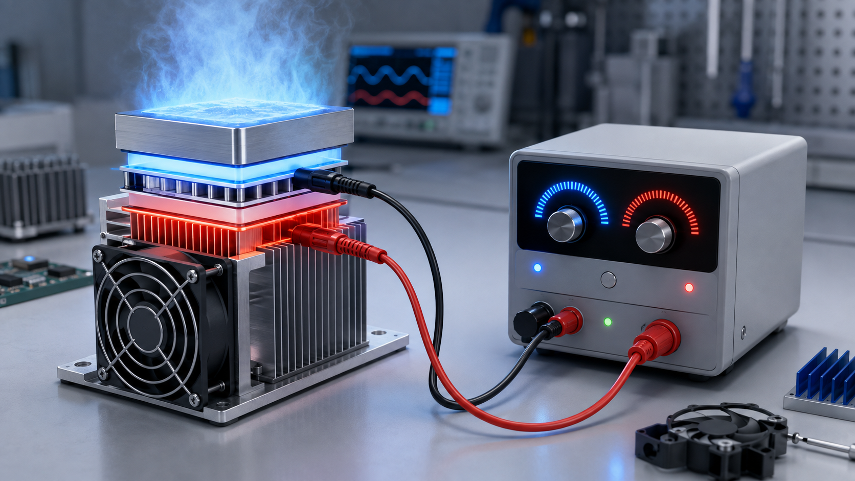
Heat dissipation is a core factor determining TEC cooling capability. Even high‑grade TECs fail to deliver expected performance if downstream heat rejection is inadequate. Three major considerations for thermal design:
- Heat sink capacity: For air‑cooled systems, heat‑sink volume, fin density, fan size and fan speed directly define the upper limit of heat dissipation. Theoretically, larger heat sinks and higher fan speeds improve cooling; however, practical selection must balance physical space constraints and noise requirements.
- Optimized air duct design: A well‑designed air duct provides defined, unobstructed intake and exhaust paths for full airflow across heat‑sink fins. Fan push‑or‑pull configuration shall be determined comprehensively based on heat‑sink geometry, air resistance and fan static‑pressure characteristics. Rather than debating blow‑versus‑pull modes, prioritize preventing air short‑circuiting, stagnant air zones and hot‑air recirculation.
- Rational intake‑and‑outlet layout: Intake and exhaust openings shall not be placed too close to each other, otherwise exhausted hot air will be re‑ingested and cause cumulative heat buildup. Ventilation openings must remain unobstructed. If vents are located on the equipment bottom, elevate the unit to avoid blocking airflow by direct contact with flat surfaces.
3. Power Supply Parameters: Electrical Matching Issues
TEC models differ in rated voltage and current. Many users neglect electrical matching and power TECs directly without parameter verification, leading to unsatisfactory cooling results. Take the widely‑used 127‑couple TEC as an example: Under‑voltage input yields insufficient cooling output. Over‑voltage operation reduces coefficient of performance while drastically increasing thermal load on the hot side.
Refer to the maximum voltage specified in the TEC datasheet for component selection and debugging. Actual operating voltage and current shall be derived from datasheet performance curves, according to target temperature difference, cold‑side thermal load and heat‑dissipation conditions. Continuous operation at maximum voltage is not recommended, as it raises thermal stress and often yields poorer net cooling effect.
Insufficient cooling from a thermoelectric cooler does not always indicate component failure. When encountering symptoms such as inadequate cooling power, failure to reach target temperatures or small temperature difference between hot and cold sides, do not jump to the conclusion that the TEC is defective. Troubleshoot sequentially from three dimensions: thermal interface, heat‑dissipation system and power‑supply matching. Verify thermal‑grease thickness and assembly clearance first; then check heat‑sink and air‑duct performance; finally confirm operating voltage and current comply with datasheet specifications, to avoid under‑powered output or efficiency loss caused by over‑voltage.