


Three CFD modeling methods to solve the matching problem of TEC system!
Thermoelectric cooling chips (TECs) are currently widely used in temperature control scenarios such as optical modules, medical devices, vehicle applications, and precision industrial equipment. However, due to the close integration of TEC application with the cooling scenario, problems such as insufficient heat dissipation at the hot end, failure to reach the target cooling temperature at the cold end, and overheating and damage of TECs often occur. This article will focus on introducing how to effectively solve the "TEC-cooling radiator-fluid" system matching problem by using CFD (Computational Fluid Dynamics) simulation.
I.Three modeling methods of the TEC model in CFD
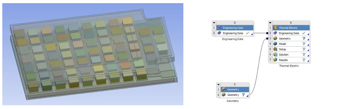
Method1: Fine Entity Modeling
Fine entity modeling typically uses the Thermal-Electric module in Workbench. This module can accurately reproduce the microscopic structures such as PN junctions, ceramic substrates, and solder layers. It not only supports the complete input of material property parameters that change with temperature, but also effectively assesses the impact of the customized distribution of the internal PN junction on the temperature control effect. During the simulation process, the following four parameter setting aspects need to be focused on:
1. Input of thermal-electric material basic parameters
Bismuth telluride (Bi₂Te₃) is the core material of commercial TEC. To ensure simulation accuracy, not only fixed values at room temperature need to be input, but also the Seebeck coefficient, resistivity, and thermal conductivity that change with temperature should be imported, and the material properties should be defined using polynomial formulas.
2. Evaluation of interface thermal resistance impact
The efficiency of TEC is closely related to the temperature difference between the two sides. Especially in high heat power scenarios, even a small interface thermal resistance can lead to additional temperature difference loss in TEC.
3. Grid division strategy
Due to the large temperature gradient within the TEC, local grid densification is necessary for the ceramic substrate and PN junction areas. The grid size is recommended to be controlled within 0.2 - 0.5 mm; at the same time, to ensure the accuracy of the flow field calculation, at least 3 layers of grids should be retained within the spacing of the heat dissipation fins, and 2 layers of grids should be retained at the ribbed areas.
4. Boundary conditions and physical model settings
Fan parameters should be directly imported from the standard P-Q curve provided by the supplier; if in a natural convection environment, the gravity option and S2S radiation model must be enabled to fully consider the influence of radiation heat transfer on the system temperature.
Method 2: Black Box Compact Model
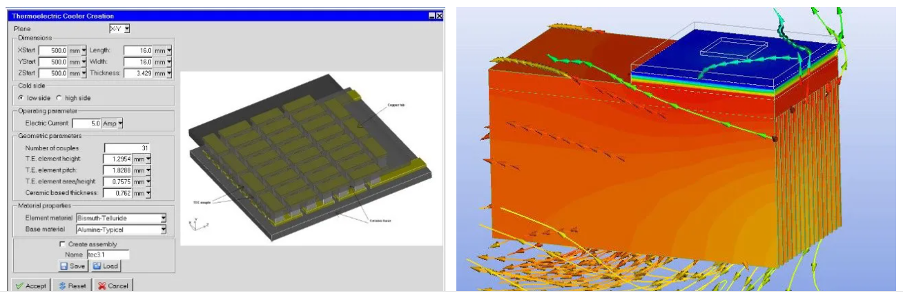
In the system-level simulation of the entire machine, the TEC component module provided by the CFD software can be directly invoked. Based on the performance parameters in the supplier's Datasheet, a two-node model can be quickly established. This method has simple parameter settings and extremely high calculation efficiency.
Taking the typical software Icepak as an example, the user only needs to input several key parameters such as the TEC shape dimensions, the thickness of the hot and cold ends of the ceramic, the number of PN junctions, height, and area. The software can automatically calculate the Peattier heat absorption, Joule heating, and cross-board heat transfer based on the input current. Besides the conventional mesh refinement and thermal resistance settings, some software supports calling a standardized TEC model library. It supports direct import and parameter adjustment, making it convenient for rapid evaluation of the scheme effect.
However, the limitation of this method is that it can only output the average temperatures at the hot and cold ends, and cannot present internal local hotspots or visualize the advantages brought by the non-uniform arrangement of PN junctions. Therefore, it is more suitable for use in the early stage of scheme iteration and the verification of the overall layout.
Method 3: Establish the complete machine model based on SW
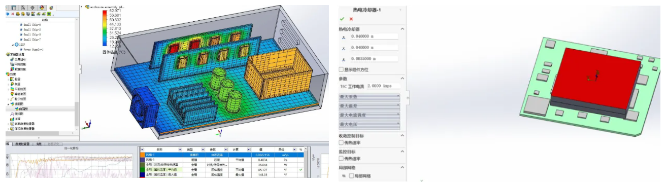
Apart from the above two methods, Flotherm XT, a product of Siemens, offers a more convenient modeling approach. Its core advantage lies in its seamless integration with 3D CAD software such as SolidWorks. Engineers can directly complete the complete machine modeling in the familiar CAD environment without switching between multiple software programs.
In terms of parameter settings, this method is also based on the two-node model. By simply inputting the two sets of temperatures provided by the TEC manufacturer for Imax, Vmax, ΔTmax, Qcmax, and the external dimensions, a thermal model can be quickly generated. Although its simulation accuracy is slightly lower than that of detailed solid modeling, it has the advantage of extremely low operational threshold and easy learning, making it suitable as a daily evaluation tool for mechanical or structural engineers who are not very familiar with complex thermal simulation settings.
II. The Value of CFD Simulation for TEC Applications
✅ Precise selection, reducing trial-and-error costs
It is not the case that the higher the current, the stronger the cooling effect of TEC. If the current is too high, it will cause a sharp increase in Joule heat, which instead leads to an increase in the temperature at the cold end. With the help of CFD simulation, different fan, radiator and TEC models can be evaluated in batches to assess their matching effects, quickly determine the optimal solution, thereby significantly reducing the number of physical prototype trials and effectively saving development costs and cycles.
✅ Optimize heat dissipation, directly addressing the temperature control pain points
The main reason for the poor temperature control ability of TEC is the insufficient heat dissipation capacity at the hot end, resulting in heat re-transportation. Through TEC-CFD simulation, the temperature field and flow field distribution on the surface of the heat dissipation components can be visually presented, helping engineers accurately identify the bottlenecks and optimize the flow path design, ensuring that the temperature at the hot end remains within the safe range at all times.
Based on 34 years of experience in the thermoelectric refrigeration industry, Qianliang Thermoelectric has deeply integrated precise simulation and thermal analysis into the entire R&D process, optimizing the thermal field design, and providing customers with a one-stop solution from custom TEC refrigeration chips to complete temperature control systems, helping to achieve efficient product development and stable operation.